|
2pc L298-Based Stepper/DC Motor Driver Board; Arduino L298N Controller Module 2x For Sale
|
 When you click on links to various merchants on this site and make a purchase, this can result in this site earning a commission. Affiliate programs and affiliations include, but are not limited to, the eBay Partner Network. When you click on links to various merchants on this site and make a purchase, this can result in this site earning a commission. Affiliate programs and affiliations include, but are not limited to, the eBay Partner Network.
Product Details ModelL298N Module
Quantity1 Assembled Module
Technical DetailsL298 DatasheetApplications2x DC Motor Driver, Stepper Motor Driver
TypeModule
Input Voltage 7-46V DC (if using 5V output)
Output Current
2A per channel
Dimensions
60mm x 55mm
Weight32g
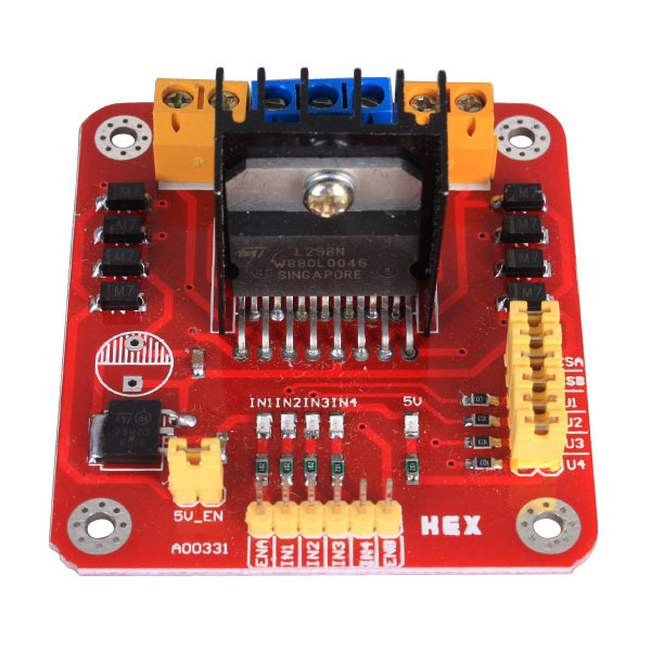
Product Information Summary:A low-cost motor driver based on the L298 dual H-bridge IC. This module will allow you to drive 2 DC motors independently (or 1 two-phase bipolar stepper motor) using logic-level inputs from an Arduino or other microcontroller board.A 5V regulator is included onboard along with an output to power your board or project without a separate regulator.All important pins are broken out to terminal blocks or 0.1" centered headers.
Operating Instructions:
- Attach motor pins to the relevant motor terminal block(s) (see pinout below)
- Remove jumpers U2 and U4
- Apply 7-46V DC to the VMS pin on the module and connect ground to GND
- To enable bridge A (motor A) apply 5V to ENA; to enable bridge B (motor B) apply 5V to ENB
Pinout: Terminal Blocks #NameDescription1A-Motor A- (OUT 2) 2 A+Motor A+ (OUT 1) 3 VMSSupply voltage 4 GNDGround5 5V 5V output 6 B-Motor B- (OUT 4) 7 B+Motor B+ (OUT 3) 6-pin 0.1" male header #NameDescription1ENABridge A enable 2 IN1Input 1 3 IN2Input 2 4 IN3Input 3 5 IN4Input 4 6 ENBBridge B and ENB enable the H-bridges A and B, respectively Jumpers U1-U4 allow for easily tying IN1-IN4 to 5V. To allow for full control of the H-Bridges remove these jumpers. IN1 and IN2 control bridge A; IN3 and IN4, bridge B. The following example specifies control of bridge A using IN1 and IN2, but the same logic applies using IN3 and IN4 to control bridge B- To move the motor forward: IN1=H, IN2=L, ENA=H
- To move the motor backwards: IN1=L, IN2=H, ENA=H
- To quickly stop the motor: IN1=L, IN2=L, ENA=H OR IN1=H, IN2=H, ENA=H
- To slowly stop the motor (free-run stop): ENA=L (IN1 and IN2 ignored)
The 5V_EN jumper enables the onboard regulatorThe CSA and CSB pins are the current sense pins for bridge A and bridge Band can be used to sense the motor current. These are also broken out to jumpered headers. If not using current sense leave the pins jumperedto groundWhen using in a parallel driver arrangement (to drive motors at up to 4A), OUT1 and OUT4 are tied together and go to one side of the motor. OUT2 and OUT3 are tied together and go to the other side of the motor. Then, to control the motor, IN1 and IN4 pins are tied together and go to an I/O pin on the microprocessor, and the IN2 and IN3 pins tied together and go to another pin on the microprocessor.  |
| | |